#
9HA (GE Gas Turbine) Combined Cycle Power Plant
Gas turbine and combined cycle
The first practical gas turbine was developed at the end do Second World War II in Europe in 1939 for aircraft. Shortly after the war, first industrial gas turbine was developed for production and other industrial application such as driving of locomotive were introducing Gas turbine use another type of cycle called the Brayton Cycle named after its inventor . The first, commercial, industrial gas turbines were relatively inefficient, typically having low thermal efficiency of 16% to 17%. Gas Turbines reached their peak of popularity in early 1970s.
The first major component of combined cycle power plant is gas turbine. In installation where the gas turbine exhausts directly to the atmosphere. It is said to in operating open cycle mode when gas turbine exhausts into the heat recovery steam generator HRSG and the resultant steam is used to operate the steam turbine generator the plant is referred to as combine cycle power plant.
Components of
Combined Cycle Power Plant (9HA-GE Gas Turbine and Steam Turbine)
Gas Turbine
Gas
turbine power plant has relatively low cost and can be quickly put into
commission it requires less space this plant Is heavy capacity and is mainly
use for peak load services. Gas turbine power plant is very promising for the
region where liquid or gas fuel Is available in large quantities common
arrangement of gas turbine driving an electric generator the gas turbine
consist of a compressor, combustion chamber, gas turbine and rotor. Air is
driven into the compressor from atmosphere, which raises the pressure pf air.
The temperature of air also increases with compression its depend upon the
design of compressor.
Gas Turbine is an internal combustion engine, like all other combustion engines, gas turbine’s compressor compress air, take in fuel for combustion, and use the resultant volume of hot gases to develop shaft horsepower. Referring the three primary sections of a gas turbine engine are:
1.Compressor
Air is drawn into the air inlet by the compressor. With-in the compressor air in compressed and at corresponding temperature rise in incurred. The hot compressed air is discharged to the combustion section of the engine,
2
.Combustor
Fuel is admitted into the combustion section by the fuel nozzles. The fuel/air mixture is ignited and combustion occurs.
Fuel is admitted into the combustion section by the fuel nozzles. The fuel/air mixture is ignited and combustion occurs.
3.
Turbine
The hot and rapidly expended gases are directed through the turbine rotor assembly. Their thermal and kinetic energy are converted into mechanical energy. The gases are expelled out to be the turbine exhaust.
The hot and rapidly expended gases are directed through the turbine rotor assembly. Their thermal and kinetic energy are converted into mechanical energy. The gases are expelled out to be the turbine exhaust.
Heat Recovery
Steam Generator (HRSG)
The
HRSG basically is a heat exchanger composed of High pressure (HP) drum, Low
Pressure (LP) drum, High pressure (HP) Super Heater, HP evaporator , HP
economizer, and LP evaporator section. These sections are positioned gas inlet
to gas outlet to maximizing the heat recovery from the gas turbine exhaust
gases The heat recover in the HRSG is used to supply steam to steam turbine at
the proper temperature and pressure. For the HRSG feed water requirements a
complete feed water system is provide composed of a feed water storage tank, LP
feed water pumps, HP feed water pumps and feed water piping system.
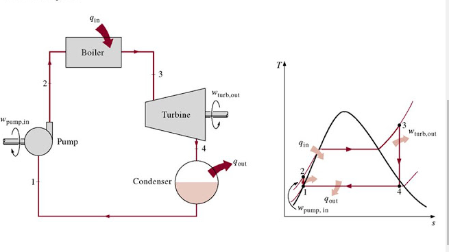
Steam Turbine
Steam
is an important medium o producing mechanical energy. Steam has the advantage
that it can be raised from water, which available in abundance. It does not
react with the material of the equipment of power plant and stable at the
temperature required in plant. Steam is used to drive steam engine, steam
turbines etc. Steam power station is most suitable where all types of fuel are available.
Thermal electrical power generation is one of the major methods. For the
thermal power plant the range of pressure may vary from (40 bar to 57bar) and
the range of temperature is (500 C to 530 C).
The
steam Turbine based components include:
·
An Energy resource in the form of flue gases to convert water into
steam: Exhaust gases (Gas turbine ) or Flue gases from burning fuel (Oil/gas)
directly in a furnace.
·
Steam generator or boiler containing water, Heat generated in the
furnace is utilizes to convert water into steam.
·
Main power unit such as a turbine to use the energy of steam and
perform work
·
Piping system to convey steam and water
·
Condenser and hot well
·
Cooling water cooling tower and Closed water circulating water pumps.
·
Condensate extraction pumps
·
Air extraction pumps
·
HP & LP Boiler feed water pumps
·
Make up water pumps
Major Electrical
Equipment In Power Plant
A
power station equipped with electrical equipment for power generation and
supply of electrical power. The major electrical equipment in power plant are
the following.
1 Generator
2 Transformers
3 Exciters
4 Circuit Breakers
5 Reactors
6 Switch Board
7 Control Board Equipment’s
8 Other Auxiliaries
Generator
It
is an importan part of a power palnt all modern types of alternating current
generators essentially consist of a fixed stator and revolving rotor
Stator
consist of following three parts
- Stator Frame
- Stator core
- Stator winding
The
stator frame is of circular in shape and is made of welded steel plates. The
core is made of stamping soft high permeability, low hysteresis and eddy
current losses. The stator is generally built in cylindrical form and diameter
of rotor is limited . Large numbers of deep slots are machined in the rotor to
accommodate the field windings which will carry field currents. Generators coupled
directly to the steam turbine are turbo generators and those coupled directly
to water turbine are called water wheel-generator.
Generator
Constants
The
following details of generator should be known to determine their performance
in the power system under different loading conditions.
1.
KVA Rating
2.
Number of Phases
3.
Frequency
4.
Number of Poles
5.
Voltage
6.
Temperature rise limits
7.
Power Factor cos ɸ
8.
Star
connection of stator
Generator Cooling
Methods
The
two methods commonly used for generator cooling are as follows:
1 Air Cooling
2 Hydrogen Cooling
Hydrogen
Cooling is far more effective than that of Air cooling because of the cooling
capacity of hydrogen. As cooling is generator is directly related to its
effectiveness to convert mechanical power into electrical energy, hydrogen
cooling is now being used in heavy duty generators to increase the production
capacities of generator as compared to that generators with air cooling.
Power Block Main Components
Main Components of a power plant include:
1 Gas Turbine-main prime mover
2 HRSG –Exhaust gas boilers
3 Steam Turbine – Secondary power prime
mover
4 Generators –
Coupled with prime movers either on same shaft or different shafts
5 Power Transformers- To step up the Voltage
produce in generator to distribute electrical power
6 Auxiliary Transformers – To step down voltages from
main generator to supply power to auxiliary components (which require much
lower voltages to that produce in main generators)
7 Breakers (on load device) – Heavy duty circuit
breakers to On and OFF high voltage lines
8 Isolators (off load device) – To electrical isolate the
equipment to ensure safety
9 Switchyard – the Station of power
transformers, isolators, Bus bars, protection relays, electrical feeders and
breakers etc.
1 Hydrogen Plant – To generate and store
hydrogen gas to fill in the generators when require
1
Water Treatment – To treat water to get
water with specific quality to ensure no corrosion, scaling, mud accumulation
and to any other treatment to be done to safe piping and related equipment.
DEMI Plant – De mineralized the water
to use for steam production
1 Fuel Gas Supply system – To supply gas at specific
pressure, temperature and quality
1 Fuel Gas Conditioning system – To treat the gas before
inserting into turbine combustion chambers
1 Liquid fuel storage tanks
and supply pumps – To
ensure quantity of liquid to be used in emergency and fuel change over
Liquid fuel Injection pumps
– To inject the liquid in
atomize form required certain high pressure pumps
Power Plant Auxiliaries
1 Gas Turbine(GT GE 9HA)
Auxiliaries
·
GT Start-up system LCI(Line
Commutated Inverter)
·
GT Turning gear motor
·
GT Lube Oil Pumps and system
·
GT Fuel Gas supply system
·
GT Liquid Fuel system
·
GT compartments exhaust and
inlet blowers for cooling
·
GT Generator Excitation
System
2 HRSG Auxiliaries
·
High Pressure Boiler Feed
water pumps
·
Low Pressure boiler Feed
water Pumps
3 Steam Turbine Auxiliaries
·
ST Lube Oil pumps and system
·
Condensate Extraction Pumps
·
ST Generator seal oil system
·
ST Generator Excitation
System
GE 9HA Gas Turbine Components
Gas Turbine plant contains parts and sections:
·
Gas Turbine
·
Gas Turbine Auxiliary
systems
·
Gas Turbine Auxiliary system
modules
·
Acoustic Enclosures
·
Generator
·
Generator Auxiliary systems
·
Electrical Starting means
·
Electrical energy evacuation
·
Power Distribution systems
It contain information related to AC and DC supply. It may include the
parts below as applicable:
1.
Battery, battery rack and related accessories
2.
Battery charger
3.
Motor control center
4.
LV switch Board Container
5.
MV Switch Board Container
6.
Container, Miscellaneous Functions
·
Control Equipment
These equipment include the parts below:
1. Packaged Electrical/ Electronic Control
Compartment (PEECC)
2. Gas Turbine speedtronic Control System (Mark-VI
E)
3. Human Machine Interface or DCS
4. Generator control System
5. Generator Protection Panel
6. Generator Excitation Panel
7. Auxiliary Panel
·
Monitoring Equipment
This volume Includes monitoring equipment such as:
1.
Vibration monitoring
2.
Hazardous gas monitor
3.
Smoke Analyzer
4.
Station Vibration Data Manager
5.
Partial Discharge Analysis Monitor
·
Balance
Of Plant (BOP Equipment)
·
Combined
Cycle(CC) Equipment
Further Insight into Gas
Turbine GE 9HA
·
Gas Turbine Instrumentation
(control/measuring devices)
·
Lubrication System
·
Cooling and Sealing Air
System
·
Trip Oil system
·
Closed Cooling Water System
(CCW)
·
Starting means system
(Turning gear & LCI/SFC/Starting Motor)
·
Gas fuel System
·
Water Injection System
·
Fire detection &
protection system
·
Hydraulic supply system
·
Heating and Ventilation
System
·
Cleaning System
·
Compressor Washing system
(off-line and 0on-line Washing)
·
Inlet Guide vanes system
(IGV)
·
Inlet and exhaust system
·
Variable Stator vanes (VSV)
·
Hazardous Gas detection
system
·
Fuel Purge system
·
Performance System
·
Liquid Fuel Inhibitor System
·
Accessory and Load gear
system
·
Miscellaneous piping
connections